

S38 Agreement blog.
- ramypatel25
- Aug 16, 2023
- 19 min read

What is a S38 Agreement.
A Section 38 agreement (or S38) is a section of the Highways Act 1980 that can be used when a developer proposes to construct a new estate road for residential, industrial or general-purpose traffic that may be offered to the Highway Authority for adoption as a public highway.
A developer may complete the construction of a road then offer it to the Highway Authority under Section 37 of the Highways Act 1980, however, S38 is more desirable, due to the fact that the council has no power to insist that a road is made up to an adoptable standard, or that it will then be offered for adoption. However, if an S38 agreement is made before construction starts, the council can ensure that it is built to the appropriate standard and is lit and drained.
The Highway Authority (council) has no power to insist that a developer enter a S38 agreement. However, many developers also see it as the better option, as the adoption process can be lengthy, and if it takes place after a road is completed, the developer will be responsible for all maintenance until adoption takes place.
Once a section 38 agreement is made, the developer will have to operate within a set of conditions, terms and timescales. It is supported by a bond or cash deposit calculated by the Highway Authority and based on the works proposed. This bond or cash deposit can be called upon if the developer goes into liquidation or otherwise defaults on their responsibilities.
The required “minimum” widths of carriageway and footways for streets in residential areas are as follows: -
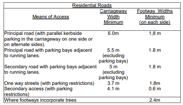
Residential Roads Means of Access Carriageway Width Minimum Footway Widths Minimum (on each side)
Many Councils have introduced 20mph borough wide speed limits, thus the recommended design speed for residential streets is 20mph.
The above minimum standards are applicable to residential streets for most developments. If however, the development is of sufficiently high density or the possibility of future extension exists or if it is considered that through traffic or extra parking may be attracted then it may be necessary to provide a carriageway width in excess of the above and footway widths compatible with the size of the development.
Cul-de-sac not to exceed 185m in length and where longer than 20m, a turning area is required.
The above carriageway widths to be a minimum of 5.5m if the length is to be traversed by buses, servicing vehicles and/or refuse vehicles.
In lightly trafficked streets the carriageway may be narrowed to a single lane as a traffic calming feature.
On secondary means of access one footway should be a minimum of 1.8m wide where more than a minimal flow of pedestrian traffic is envisaged.
Where pedestrian routes are provided remote from the carriageway then verges of 0.6m wide will be provided to accommodate vehicular overhang and occasional pedestrian movement.
Kerb Radii
For residential roads and principal means of access the kerb radius at junctions will normally be 6 metres or approved compound kerb radii. Dropped kerbed pedestrian crossings with tactiles are required at junctions. At junctions where corner radii is less than 6m then the footway shall be strengthened with 150mm sub base combined with 80mm thick blocks laid in herringbone pattern on 50mm thick sand bed.
Junctions
Most junction arrangements take the form of a priority junction where the footways can be constructed with grey blocks in the quadrant formed by the radii. T types staggered or crossroads are normally appropriate where traffic flows to and from minor roads are relatively light. Where flows are heavier, or layouts are complex then other types of control are required. Junction alterations require the developer to enter into a Section 278 Agreement.
Junctions involving Strategic Routes or traffic signals will require Transport for London Approval. In general junctions with London Distributor Routes shall be in accordance with the Design Manual for Roads and Bridges Volume 2. Some junctions may require entry treatments in accordance with the Council highway details (available upon request from the Engineering Manager). It is recommended that early stage discussion regarding the junction type, design and location should be held with the Engineer.
Dropped Kerbs/Crossovers Ramped ‘Dropped Kerb’
Vehicular crossings should be used in lieu of kerb radii and quadrants. Individual garage access should, where possible, be dualled and ramps shall not be steeper than a gradient of 1 in 10. On private driveways gradients may be increased to 1 in 8 on sites where level differences make it impractical to use fewer steep gradients. To avoid vehicles grounding on private drives the gradient should be maintained at 1 in 10 for at least 1.5m from the back of footway or include a vehicle roll over between the gradients. Crossovers widths up to a maximum or 4.5m. Where an access has a total width exceeding 4.1m and serves a multiple parking area, then kerb radii is preferred. Dropper kerbs shall be of minimum length 900mm, unless otherwise agreed with the Engineer. A crossover fee of £110 and an application is required for that served of the public highway and can be found on: https://lewisham.gov.uk/myservices/parking/crossovers-- dropped-kerbs-and-white lines
Forward Visibility and Sight Lines
The vertical and horizontal alignment of carriageways should be such that a forward visibility is maintained commensurate with likely vehicular speeds. The ‘minimum’ acceptable forward visibility is 25 m SSD (stopping sight distance for 20mph) and 43 m SSD (stopping sight distance for 30mph). There will be situations where traffic speed can be controlled by reducing forward visibility. The forward visibility splay envelope along the road edge at radii will be dependent upon traffic and pedestrian volumes. Ideally parking should be omitted from the forward visibility splay.
Changes in alignment of the carriageway will be designed to maintain an acceptable forward visibility. Where the forward visibility line crosses an area behind the highway boundary, it will be necessary to ensure that this area remains clear and unobstructed from a height of 0.6 metres above back of footway level. This requirement will not affect established trees where the foliage is above 3 m high. For all road types within a development, visibility (at junctions, bends or crests) in the vertical plane should normally be measured from a driver’s eye-height of no less than 1.05m above the road surface to a point no less than 0.6m above the road surface.

Parking bays should not be located within forward visibility lines and in visibility splays. The impact of street furniture on visibility should be assessed as part of the Road Safety Audits. Sight lines in accordance with these standards should be provided for all new vehicle accesses. Where existing accesses are utilised or their use intensified, every effort should be made to secure the best sight lines while being sympathetic to the visual appearance of the street.
Visibility Splay and the Production of Adequate Sight Line at Junctions and Bends
Suitable splays are to be provided at road junctions. A minimum splay will be produced by a straight line between the points of intersection of the back line of path with lines joining those tangent points and the centre of radius, as indicated in diagram 2.
(i) A line ‘x’ m long is measured along the centre line of the side road back from the continuation of the nearer edge of the major road carriageway.
(ii) (ii) A line ‘y’ m long is measured along the nearer edge of the major road carriageway from its intersection with the centre line of the side road.
(iii) (iii) The sight line is obtained by producing a straight line joining the ends of the above lines. In certain circumstances where the sight line to the left is difficult to obtain it may be permissible for the ‘y’ distance to be measured along the centre line of the major road carriageway.
(iv) (iv) Where the junction is on a bend in the major road the whole of the major road carriageway is to be visible to drivers in the side road within the bounds of the ‘x’ and ‘y’ distances. This may involve moving the ‘y’ line back so that it meets the major road kerb line tangentially.

Type of Road Design Speed/ Speed Limit ‘x’ m Desirable ‘x’ m Minimum y’ m minimum District Road of Traffic
Turning Facilities
Road layouts should, where possible, be designed to eliminate the need for drivers to make 3-point turns. The minimum dimensions of turning facilities at the end of cul-de-sac in residential roads are shown on Diagram 3. Vehicle swept paths for 11.2m length large refuse vehicle will need to be demonstrated. Motorists tend to park in areas designed to accommodate turning vehicles and it is good practice to extend the arms of the turning heads by 5m to accommodate this.

Refuse Collection
Routeing for refuse vehicles should be considered at concept design stage and where possible designed to eliminate the need for reversing. Roads for refuse collection should have a minimum width of 5m and any pinch points 3.7m. Clear minimum height of 4.5m for any overhead fixtures. The maximum haul for bins is 10m from the collection point to the kerb line.
Parking Provision
The developers should refer to the most recent Borough Parking Policy. On and off-street parking provision should meet the standards set in the Council’s Local Development Framework. The location of car parking areas in a development should be considered at an early stage in the design process to achieve a balanced distribution of spaces throughout the site and be conveniently related for residents. Pedestrian access routes to parking should be designed so that it is easier and more convenient to use the designated parking areas than to park casually on the road. Special consideration to be given to the needs of disabled people. It should be noted that generally the Council does not allow disabled parking provision on the existing public highway network for new developments.
Parking spaces, where provided, should be 2.4m x 4.8m for parallel and perpendicular parking with a 6m clear carriageway manoeuvring space. Reference to be made to Manual for Streets 2007 for parking layout design. Longer bays will be required in certain situations and bays provided for the ambulant disabled and wheelchair users should be 3.3m wide. Partial and footway parking should not design into new roads. Where there is a need to regulate parking then this should be done by making appropriate traffic order regulations.
Traffic Calming
The Council has a policy of a borough wide 20mph limit and consequently all new roads should be designed for this limit. Where there are valid reasons why vehicle speeds cannot be controlled through site layout then traffic calming measures may be used to achieve this, but such consideration should be given to horizontal measures first and vertical measures second.
Where traffic calming is proposed then the Developer will need to consult the emergency services at an early stage. Most Councils uses sinusoidal humps, height 75mm+/-5mm with length of 3.7m. Usual spacing of 70m with a maximum of 100m. Raised junctions/Flat topped tables/Entry treatments may be appropriate for traffic calming at junctions, informal crossings or along routes.
Along bus and emergency services routes a 6m plateau is required with 1 in 20 ramps with a maximum height of 75mm+/-5mm. These can be formed of asphalt, but where block pavers or mixture of both is used then granite kerb restraints are required on the top of the ramp. Tactile paving to be installed where footway level is at grade. Flat top and junction entry treatments require a plateau length of a minimum of 2.5m and sinusoidal ramps. Speed cushions are usually only installed on emergency service and bus routes. In Lewisham a height 75mm+/-5mm with nominal length of 2.5m and width of 2m (for bus route 1.6m to 1.7m is preferred). Maximum spacing for cushions of 70m. Where any form of vertical calming feature is proposed, it should not be sited within 25m of the edge of a structure, for example, a bridge or culvert.
They should also be sited clear of private accesses and driveways to avoid problems of vehicles ‘grounding’.
Signing and Reducing Clutter
Designers should begin by assuming a total absence of signs and only introduce them if they serve a clear function. There may be situations where there is an opportunity to reduce the existing sign clutter. The Traffic Signs Regulations and General Directions 2016 (TSRGD) details traffic sign and road marking prescribed for use in the UK. Compliance with TSRGD is mandatory. The impact of street clutter to be minimised by mounting signs on columns, consideration of streetlights onto buildings, bin stores off the footway, specifying orientation of inspection covers in footways. Mounting signs on existing columns will require approval from Councils.
Shared Surfaces
Shared surfaces can work in short lengths, cul-de-sacs or where traffic volumes and speeds are low. Usual surfacing material to be block paviours. Shared surfaces to include an alternative route for the visually impaired. The developer should refer to “Effective kerb heights for Blind and Partially Sighted People” by UCL Accessibility Research Group – 2009. In this document it is recommended to install kerb height 60mm or greater. Any detraction from this recommendation will need to be addressed in Road Safety Audits Parking spaces within shared surfaces to be clearly delineated e.g., through change of material.
Footpath Routes
The developer should delineate suitable routes for pedestrians, including those with prams and wheelchairs. These routes should have a firm, non-slip surface and avoid steps even if this means slightly longer ramped routes. Steep cross-falls, gratings likely to trap wheels and obstruction by lighting columns, signposts etc, should also be avoided. Long ramps should include rest platforms and there should be level areas at the top of each ramp and at every change in direction.
Width of Footpaths for Prams and Wheelchairs
On footpaths or footways where it is likely that prams or wheelchairs will be used, the width should at no point be less than 1800 mm.
Demarcation of Highway Boundary
Wherever the extent of the adoptable highway is not clear - for example there is no wall, fence or edging to the footway - then an agreed form of boundary marking to be installed. Usual demarcation to be with brass studs or a row of “hit and miss” granite setts.
Disabled Persons
It is a statutory requirement to have regard to the needs of disabled people in designing any building to which the public have access. This will include the provision of suitable access routes for wheelchairs and the marking out of parking spaces close to pedestrian entrances for use by disabled people. Disabled parking bays on the public highway should not be integral to the layout design of the development.
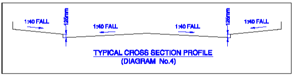
Gradients of Carriageways and Footways
Channel Gradients are not normally to be less than 1 in 120 but may be reduced to 1 in 200 by using channel blocks in order to assist surface water drainage. Slot drains to be avoided. Minimum longitudinal gradient 1 in 125 for flexible surfacing and 1 in 80 for block paving surfacing. Maximum gradient 1 in 16.7 and 1 in 14.3 for shared surface environments. Cross sections shall normally be designed at 1 in 40 and a cambered design is preferred. Super elevation should be incorporated in the design of all curves, and in some instances will be essential. The changeover from camber to cross-fall is normally on the straight section of the road. Longitudinal gradients for footways are normally the same as the adjacent highway. The recommended cross-fall gradients are between 1 in 50 to 1 in 30.
Vertical Curves
Where changes in gradient occur, vertical curves will be required at crests and sags. Length of curve derived from the formula L=KA. Where K minimum is 6.5 for a 30mph road and a minimum 3 for a 20mph road. The minimum length of vertical curve is 30m for 30mph and 20m for 20mph. A is the algebraic difference of the gradients expressed as a percentage. For crests it may be necessary to increase the length of the vertical curve in order to achieve the visibility distance (43m for 30mph and 25m for 20mph).
Footpath Gradients
For routes designed for pedestrians with prams or wheelchairs, desirable gradients 1 in 80 to a recommended maximum of 1 in 20 and with an absolute maximum of 1 in 12.
Steps
Steps pose problems not only for those with prams and wheelchairs but also for subsequent mechanised maintenance and should never form the sole pedestrian route. However, since some people find walking on any sloping surface difficult or impossible, steps should be provided in additions to ramps where possible. Flights should comprise between three and twelve steps and longer flights should be split into sections by landings. Steps should be provided with handrails, have permanently non-slip treads, and have a minimum width of 1200 mm clear between handrails.
Handrails
Handrails should be Equality Act 2010 compliant, contrast visually, be easily gripped, and must be securely fixed. They should be provided at both sides of the steps (or centrally on step 3 m wide or over) so they can be used by either hand and extended well beyond the top and bottom nosing’s.
Highway Profile
The profile of the highway is to be such that surface water will drain naturally into the channels. The footways will fall towards the kerbs with a gradient of 1 in 40 for slabs and 1 in 30 for bituminous materials. The kerb upstand will generally be 125 mm except where the natural longitudinal gradients of the site are such that false gradients must be introduced into the channels when the kerb upstand may be varied between the limits of 100-160 mm. 150 x 300mm granite kerbs are the normal. Bus stop kerb heights to be 125-140mm. Concrete kerbs are only used on existing roads where granite kerbs are not used. The carriageway profile will be determined by reference to ‘Gradients of Carriageways’ above.
Kerbs
150mm x 300mm granite kerbs fine picked laid upright, straight and radii, as detail. 300mm flat kerbs only where matching into existing. Natural stone kerbs should be supplied from a single source to ensure consistency. If reclaimed natural rock kerbs are used, they shall be redressed before use.
If there is a variation in sizes in the supply of kerbs the equivalent sized kerbs must be used together. Kerbs shall be laid on a wet concrete bed or mortar bed. Re-used granite kerbs to be agreed with the Engineer, or his representative, before laying. The Engineer, or his representative, will determine whether kerbs can be reused, rejected or are required to be re-dressed. Kerbs to be considered for reuse to be examined for; frost, scuffing, durability or appearance and other damage.
Re-used kerbs are not to be mixed with new kerbs and should only be consecutively used. Any impaired kerbs shall be rejected. Where additional reclaimed kerbs are required, they should be chosen to match the originals. Older granite kerbs are not often dressed to a standard profile, finish and size and thus should not be mixed with new kerbs. Kerb under 450mm in length will not be considered for re-use. Precast concrete kerbs will only be used where they match the existing kerbs, on the public highway only, and require the approval of the Engineer.
For all extensions to the highway network only be granite kerbs will be accepted. Conservation type kerbs are not accepted as an alternative to granite.
Granite Setts
The use of large areas of granite setts is to be generally avoided, particularly those with irregular surface. Prior discussion with the Engineer is required at an early design stage where the use of granite setts or pavers are proposed. In exceptional circumstances where granite paving is used then they shall be 100mm wide and deep bedded and pointed with 10mm mortar mix designated and where in carriageway ramps to be laid with an approved BS 7533 bedding and pointing (eg Instarmac-Ultrascape or similar approved) as referred to in “Design for Pavements” section in this document. Granite sett delineation of the highway boundary is acceptable.
Footways and Tree Root Protection Areas
Traditional pre-cast concrete paving is preferred extended kerb to back of footway. Regular traverse bond across to footway at 90 degrees to the kerb (bond stagger 150mm). Mortar infill to be avoided and close butt joints should be provided.
Recessed inspection covers in footways where paviours or York stone used. Stronger paving should be used in areas where vehicles are likely to use the footway regularly (e.g., footway parking and in delivery areas). Slabs such as the 400mm x 400mm x 65mm slab can withstand regular use by vehicles up to the maximum legal road-going weight, including vehicles that use stabilisers. Where the footway works are on an existing footway with trees, then tree roots to be protected during the construction.
Flexible footway construction of asphaltic concrete or resin bound material to the tree root areas is required. No mechanical excavation is allowed in a root protection area (RPA) and excavation and construction to be established with the Council’s Arboriculturist.
Drainage
Highway drains should, where possible, discharge into the existing sewers. The length of highway drainage to be kept to a minimum and should be designed to include only gullies and their connections.
The Council’s design details for gullies are included in most Councils Standard details document. We will not normally accept a combined kerb and drainage system. We will not normally accept drainage of other non-adopted areas discharging onto the highway or into an existing or an adoptable highway drain. Downpipes not to be sited within the proposed and existing highway boundary area.
Where private non-adoptable drives and other surfaces fall towards the adoptable highway, the design must prevent surface water run-off from reaching the highway boundary and entering the highway drainage system.
Gullies are to be sited at suitable points at an optimum spacing of 200m2 of impermeable drained area per gully. At summits the first gully should not be more than 45m from the high point. Double gullies to be provided at sag points with individual connections to the sewer.
Cycle friendly gully covers on designated cycle routes. Gullies to be sited upstream of the tangent point at road junctions. Gullies should not be sited directly at pedestrian crossing points but located where practical upstream of the crossing points. Gullies should preferably connect directly into manholes, but if this is not possible, they shall be connected to the main pipe by 45 degree oblique angled junction or saddled at an oblique angle and surrounded by ST2 concrete mix.
New gullies should not be connected to an existing gully run where they increase the surface water run off area and/or the distance is greater than 5m. Longer distances require a new direct connection. Gully run lengths to be a maximum of 15m and there should be a separate connection for each gully.
A maximum of two gullies is allowed on one carrier drain connection. Concrete and polypropylene linear type channel drainage to be avoided. Catch pits or chute gullies are to be avoided and can only be used, on the existing highway where there is insufficient depth to install a pot and they must not connect to another catch pit. Weir gullies should only be used in exceptional circumstances, and on the existing highway, where there are statutory plant diversions required to install a gully pot and/or where the outlet pipe is directly towards the sewer.
The minimum pipe diameter for adoptable highway drains, other than gully connections, is 225mm. Single gully connections to be 150mm diameter. Highway drainage manhole spacing’s at a maximum of every 50m, change in direction or at connections. Under no circumstances should manholes be laid within carriageway junctions or in roundabouts. The pipe cover shall at least be 1.2m within the carriageway and 0.9m elsewhere. If minimum cover cannot be provided, then super strength clay or heavy strength concrete pipe to be provided surrounded by 150mm ST2 mix concrete with flexible joints.
The edge of the excavation for highway drains should not be closer than 600mm to the new kerb line. A minimum of 150mm clearance should be maintained where pipes cross any other piped or ducted service. Where SUDS are proposed for highway drainage, then the Developer must enter discussions with all relevant parties at an early stage (and certainly before any planning application) to agree ownership and responsibility for the facility. SUDS often result in higher maintenance costs which will need to be reimbursed through the legal agreement.
Non-standard drainage systems are not usually adopted. Standard drainage systems include pipes, manholes and gullies. Non-standard systems include culverts, linear drainage, flow attenuation systems, pollution control devices and SUDS. If the Council adopts SUDS and non-standard drain elements, we will require a commuted sum to cover future maintenance.
Dropped Kerbs at Road Junctions
Gradient 1:20 preferred, 1:12 maximum. Width minimum 1.2m. Provisions should be made at all road junctions for pedestrians to continue along the major road, with a minimum of inconvenience. Kerbs should, therefore, be “dropped”, flush with the carriageway in line with the pedestrian route.
Tactile Paving
400 x 400 x 65mm Tactile paving should be installed in accordance with “Guidance on the use of Tactile Paving Surfaces”, Department for Transport. Red at controlled crossings, yellow or charcoal grey at uncontrolled. Ladder and corduroy paving to be charcoal grey. In conservation areas charcoal grey or York stone tactiles may be used.
Soft Landscaping
Soft landscaping to be limited to trees only with a minimum 14-16cm girth. Species to be agreed with the Engineer. Resin bonded 10-15mm gravel to tree surround with granite or sett edging. In most cases a 5-year maintenance period will be specified in the Agreement for soft landscaping areas. Tree pit construction as detailed in Council Standard Details. Alternative, soft cell type tree pit construction will require approval from the Engineer and should only be considered for installation on the existing highway network.
Footway Crossings
Light duty domestic vehicular crossovers shall be constructed of concrete (generally grey) block paving and only bituminous surfacing where matching the existing. 150mm x 50mm square-topped precast concrete edgings shall be laid along both edges of the crossover and at the garden boundary, prior to construction of the crossover surfacing.
Heavy duty industrial crossovers shall be constructed as shown in Council Standard Details. Where vehicular access to premises is taken across a footway the ramped portion should be confined to that immediately adjacent to the carriageway, thus emphasising the pedestrian right of way. The crossing to have a 25mm kerb upstand. The short ramp adjacent to the kerb also encourages a reduction in the speed of vehicles crossing the footway. Vehicular crossovers with high traffic flow to be treated as an uncontrolled crossing at a side road and tactile surfacing should be installed.
Road Markings
Road markings from hot applied thermoplastic screed with glass beads. All markings in accordance with the Regulations. Generally 75mm thick yellow lines but primrose yellow 50mm thick in conservation areas. Cold applied, resin binder with aggregate and a 5-year guarantee, line markings (Safe track LM - GCP Applied Technologies, or similar approved) to be used at junctions and where specified by Engineer for sites with high traffic use and also on traffic calming features.
Highway Structures (including Basements adjacent to the Highway)
Any proposed structures for adoption or basements adjacent to the highway will require approval by the Council’s Engineer. The Approval in Principle (AIP) process is as set out in: standardsforhighways.co.uk Where structures are adjacent to or on TfL highways please refer to structurestechnicalapproval@tfl.gov.uk for any approvals that are required.
Drainage associated with the Highway.
Where sewers and drainage work have to be provided within the area of the highway, the specification required for their construction shall be in accordance with the utility requirements. The Council’s standard details for highway drainage are that in its standard details and that in the Specification for Highway Works.
Street Lighting
The developer will be required to provide and design the street lighting to standards as set out within the Councils Street Lighting Standard Development Specification”. A design pack is required which will show the highway details, design criteria, maintenance factor, lighting class, design lighting levels. Drawings to be submitted showing the existing and proposed lighting layout. The street lighting Service Provider can be contacted for rates to carry out street lighting design and installation for the Developer.
Street Name Plates
The developer will be required to provide street name plates, as specified, at the end of each new highway.
Antiskid Surfacing
High friction surfacing on the approaches to signal-controlled junctions, roundabouts and pedestrian crossings are required where it is specifically required by TfL or the Council. At signal-controlled crossings a higher PSV 68 surfacing is an acceptable alternative for the borough.
Anti-skid surfacing can be bituminous extended epoxy resin with 1-3mm bauxite, and the existing road surface condition needs to be appropriate to accommodate this surfacing. Alternatively, a resin binder with aggregate to last a minimum of 5 years in high-risk areas, as required by the Engineer. This existing surfacing condition to be agreed with the Engineer for any necessary patching works to be carried out prior to applying the anti-skid surfacing.
This high friction surfacing to be applied for a minimum length of 50m ahead of the stopline on roads subject to a 20 or 30 mph limit, but an increased length may be required due to the approach speed, accident record, average queue length, proximity of side roads and mix of traffic. On approaches to pedestrian crossings the high friction surfacing should be continued past the stop-line to the first line of crossing studs. To reduce the risk of high friction surface systems failing too soon after application, they are to be applied to a dry surface and where the surface courses have been used by traffic for some weeks before the surfacing is installed.

Comments